Reference: 10HS ECHO - 5Mts

Reference: 10HS ECHO - 5Mts
Reference: BASE-U-4
Reference: UA-002-64
Brand: ONSET
Reference: VH400-2M
Brand: VEGETRONIX
Reference: DS1922E-F5
Brand: iBUTTON MAXIM INTEGRATED


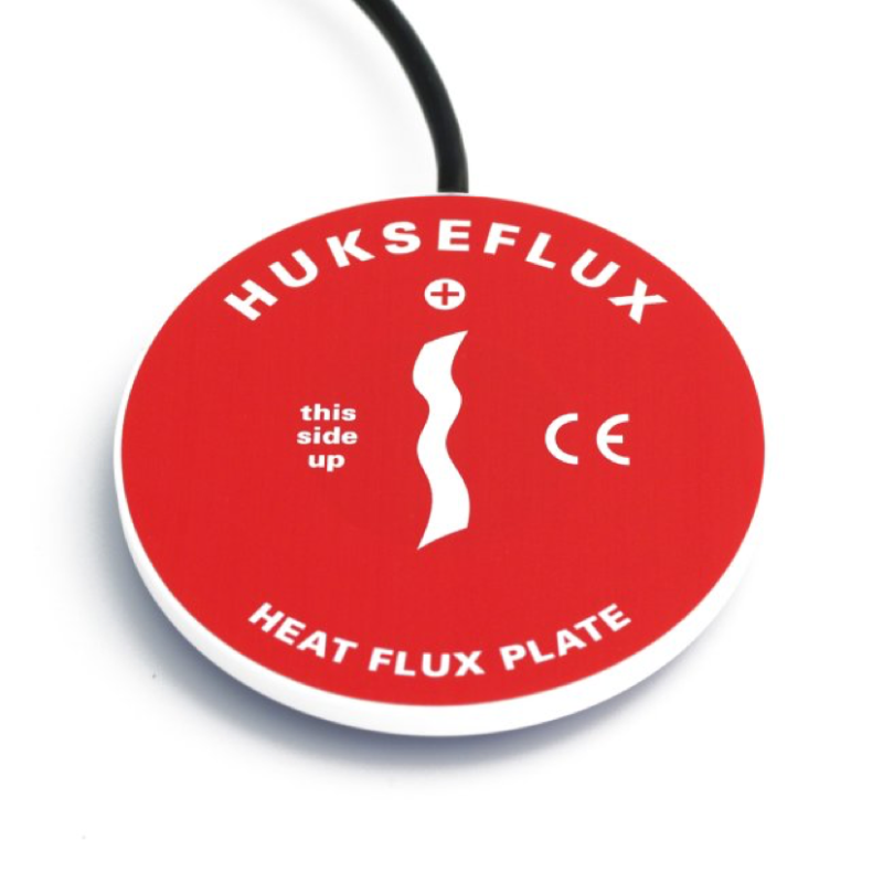
Heat flux plate
HFP01 is the world’s most popular sensor for heat flux measurement in the soil as well as through walls and building envelopes. The total thermal resistance is kept small by using a ceramics-plastic composite body. The sensor is very robust and stable. It is suitable for long term use on one location as well as repeated installation when a measuring system is used at multiple locations. If measuring in soil, in case a more accurate measurement is needed the model HFP01SC should be considered.
| Measurand |
| heat flux |
| Measurement range |
| -2000 to +2000 W/m² |
| Sensitivity (nominal) |
| 60 x 10⁻⁶ V/(W/m²) |
| Sensing area |
| 8 x 10⁻⁴ m² |
| Guard width to thickness ratio |
| 5 m/m (as required by ISO 9869 D.3.1) |
| Sensor thermal resistance |
| 71 x 10⁻⁴ K/(W/m²) |
| Sensor thickness |
| 5.4 x 10⁻³ m |
| Uncertainty of calibration |
| ± 3 % (k = 2) |
| Rated operating temperature range |
| -30 to +70 °C |
| Cable diameter |
| 4 x 10⁻³ m |
| IP protection class |
| IP67 |
| Standard cable length |
| 5 m |
Description
The world’s most popular sensor for heat flux measurement
HFP01 measures heat flux through the object in which it is incorporated or on which it is mounted, in W/m². The sensor in HFP01 is a thermopile. This thermopile measures the temperature difference across the ceramics-plastic composite body of HFP01. A thermopile is a passive sensor; it does not require power. Using HFP01 is easy. It can be connected directly to commonly used data logging systems. The heat flux in W/m² is calculated by dividing the HFP01 output, a small voltage, by the sensitivity. The sensitivity is provided with HFP01 on its calibration certificate. A typical measurement location is equipped with 2 or more sensors. HFP01 is the world’s most popular sensor for heat flux measurement in the soil as well as through walls and building envelopes.
Robust and stable
Equipped with heavy-duty cabling, protective covers on both sides and potted so that moisture does not penetrate the sensor, HFP01 has proven to be very robust and stable. It survives longterm installation in soils, as well as repeated installation when a measuring system such as TRSYS20 is used at multiple locations.
BLK and GLD Sticker Series
Would you like to study energy transport/heat flow in detail? Hukseflux helps you take your measurements to the next level: order the HFP01 with black stickers that absorb radiation and gold stickers that reflect radiation. This way, you can measure both convective and radiative flux with one, and only convective flux with the other. Subtract the 2 measurements and you get the radiative flux. The BLK – GLD stickers can be applied to the sensor by the user. Optionally, they can be ordered already applied. See the user manual and installation video for the BLK – GLD sticker series for instructions.
How to Install a Heat Flow Sensor
Tips and Tricks to Get the Most Out of Heat Flow Measurement
Heat flow measurement is a powerful tool for gaining insight into processes. It can measure, for example, how much heat is flowing through a wall or into a sample that needs to be cooled. Assuming the right sensor is used, installing this sensor correctly, so that it makes a stable measurement and measures the correct heat flow (radiative and convective), is a critical step in getting the right data. This paper takes an in-depth look at the do's and don'ts of installing a heat flow sensor.
Introduction
Heat flow sensors have a wide variety of applications, from analyzing the thermal performance of thermal insulation to monitoring pipe fouling and monitoring the health of pigs. Measuring heat flow can yield useful insights into processes and system performance. Assuming the right sensor is used, mounting it correctly, so that it makes a stable measurement and measures the correct heat flux (radiative and convective), is a critical step in obtaining the right data.
This document focuses on sensor installation. What are the dos and don'ts when installing a heat flux sensor? How can you get the best data from your sensor?
General considerations for heat flux measurement
Use the right sensor for the application. There are many different models, each with its own temperature range and heat flux. See our full range of heat flux sensor products.
Also see our YouTube video: How to measure heat flux.
Take a representative measurement. This starts with choosing the right location, representative of the system to be monitored. Use multiple sensors. Representativeness can be checked using infrared cameras.
Installation Considerations
Regardless of the type of heat flux sensor, it is important that it is securely mounted to avoid variations in contact resistance between the sensor and the object on which it is mounted.
Air gaps between the sensor and the object can be significant thermal resistances and increase response time. This should be avoided.
Sensors that gradually loosen produce unreliable (seemingly unstable) measurements. Use a stable glue or filler. Use high-quality cables and strain relief.
Also, the optical properties must match.
Pay attention to the optical properties of the sensor surface. These must match those of the object on which the sensor is mounted.
Mounting
There are several ways to mount a heat flux sensor, depending on the application. Two important parameters are:
the temperature range
the measurement duration
These two parameters will help you choose the right mounting solution for the heat flux sensor. Table 1 and the examples at the end of this note will help you review your options.
Always make sure the cable has a strain relief to avoid unnecessary stress on the sensor.
Why avoid air gaps
The thermal conductivity of air is on the order of 0.02 W/(m K). Therefore, even small air gaps are significant thermal resistances.
The thermal conductivity of a plastic or thermal paste is on the order of 0.2 W/(m K), so for the same thickness, the thermal resistance is a factor of 10 lower.
Let's take an air gap of 0.05 x 10⁻³ m as an example. This has a thermal resistance of 20 x 10⁻⁴ K/(W/m²). This can be compared to 11 x 10-⁴ K/(W/m²) for the FHF05 series or 70 x 10-⁴ K/(W/m²) for HFP01, whereby a small air gap results in an increase in thermal resistance of respectively 200% for FHF and approximately 30% for HFP01. Using a 0.05 x 10⁻³ m filler, with a thermal conductivity about 10 times that of air, the thermal resistance is reduced to 2.5 x 10-⁴ K/(W/m²). The thermal resistance contribution is reduced to approximately 20% for FHF05 and 3% for HFP01.
It can also be seen from this example that it is not necessary to use high thermal conductivity tapes. Using a normal thin tape is sufficient.
An air gap can not only lead to increased thermal resistance for conductive heat, but also to a completely different radiation balance. An air gap is a "resistance" (a radiation screen) for radiative transfer. If it is filled, it no longer provides resistance. Be careful in case the radiative (far infrared) heat flux is significant. In that case, the presence of an air gap can be the main source of errors, as a sensor with an air gap acts as a radiation shield, reducing local radiative transfer by a theoretical maximum of 50%.
What to do with air gaps
Tapes, sheet material (gaskets), glues and cements can be used to fill air gaps.
These gaps can occur:
due to the nature of the surface. It may not be smooth. Smooth it out before installation
due to a curvature in the surface. For all practical purposes, a surface with a radius less than 5 m is considered "flat". For smaller radii, the use of flexible sensors can be considered. For industrial sensors such as IHF01 and IHF02, we can also provide coupling pieces (flat on one side, curved on the other).
Your review appreciation cannot be sent
Report comment
Report sent
Your report cannot be sent
Write your review
Review sent
Your review cannot be sent
Reference: M2 T
Brand: tempmate
Reference: RTR507BL
Brand: TandD
Reference: U0121M
Reference: SBG04
Brand: Hukseflux
Reference: SBG01
Brand: Hukseflux
Reference: P3110E
Brand: COMET
Reference: H3531
Brand: COMET
Reference: RK310-02
Brand: RIKA SENSORS
Reference: M1 tempmate
Brand: tempmate
Reference: MX1104-TEMP-06
Brand: ONSET
Reference: HE171
Brand: HUATO
Reference: TPF/1-E
Brand: FUEHLER SYSTEME
Reference: S635-LUX-UV
Brand: HUATO
Reference: RK330-01A - 4-20mA
Brand: RIKA SENSORS
Reference: C1 tempmate
Brand: tempmate
Reference: UA-002-64
Brand: ONSET

Heat flux plate
HFP01 is the world’s most popular sensor for heat flux measurement in the soil as well as through walls and building envelopes. The total thermal resistance is kept small by using a ceramics-plastic composite body. The sensor is very robust and stable. It is suitable for long term use on one location as well as repeated installation when a measuring system is used at multiple locations. If measuring in soil, in case a more accurate measurement is needed the model HFP01SC should be considered.
check_circle
check_circle